How I hacked a cheap remote control using an arduino
Prologue:
One fine day I thought that it would be a good idea to order a cheap chinese remote controlled light switch. I liked it so much, it made my life easier. I could just turn off and turn on the lights. No more walking to the bed in the dark! It has this nice little remote control. I should have gone for the wifi one. It looks so nice I do not want to throw it out. So I grabbed my arduino, sensors, wifi module and made a little gadget that allowed me to control my light with wifi.
A few months later I went to the dentist and saw that the door was remote controlled. I saw the same little remote control again! Must be a special case I thought. Few days later, I went for a job interview. The remote control was there. Again. Just like when you buy a new car and suddenly you start to see it everywhere. But one month before that you could not find a single one on the street. I now realize, these are everywhere. Need to make a device to hack them.
Main Idea
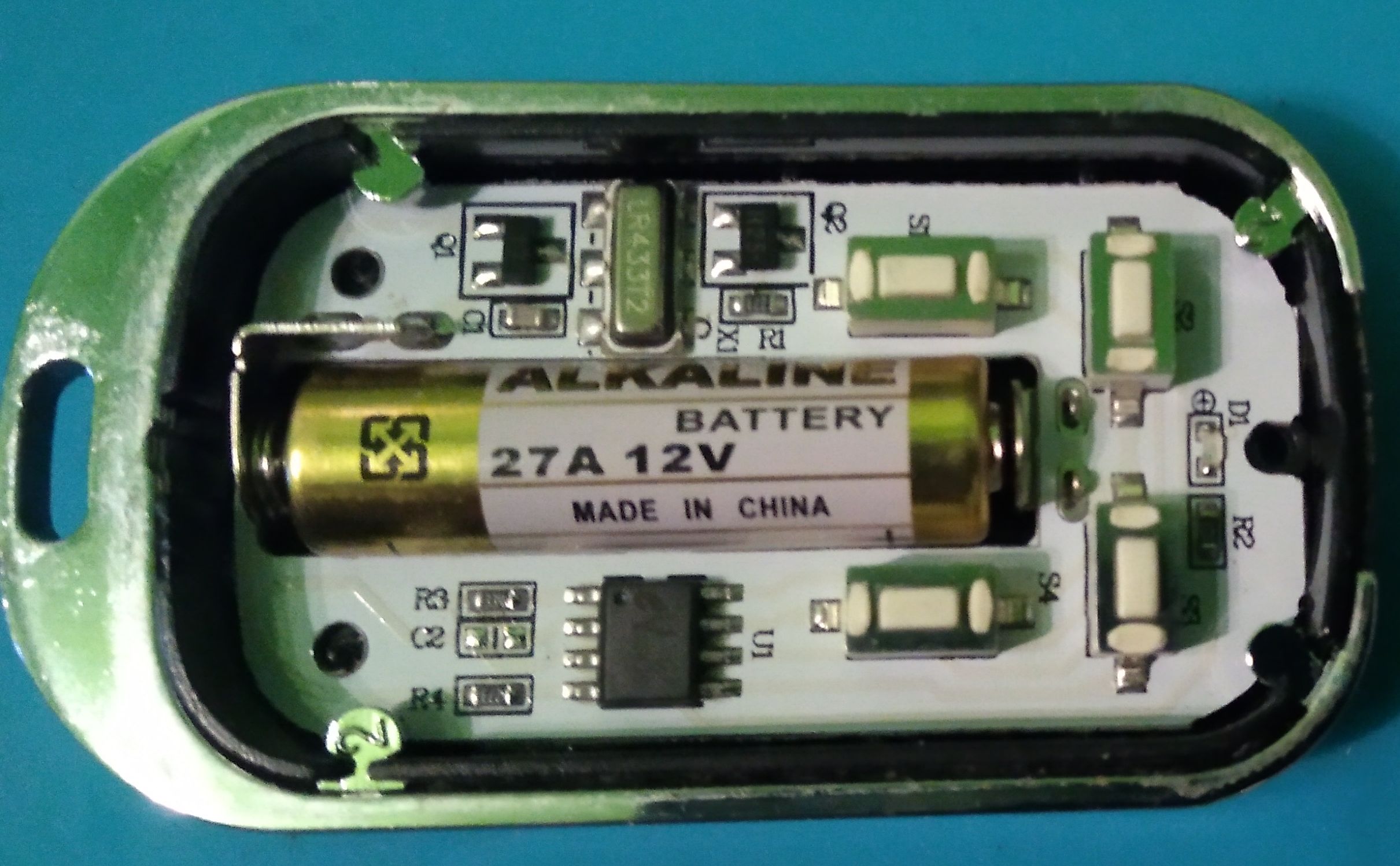
Sometimes the easiest way can work really well. If we want to control something and we do not have the remote control, we can just try to figure out how it works. In this case, a quick googling told me that this is a remote control working on the frequency of 433 Mhz. That is not enough. So I opened the device. I saw a EV1527 chip there. Quick googling and I found out that it has a few codes pre-programmed inside. No changing code, no encryption, literally nothing! No security whatsoever!
From there on my objective was clear. Grab the code, and try to replay it. Simple, easy, it should work. That is the basic idea for hacking most of the cheap remote controls.
Back to the basics
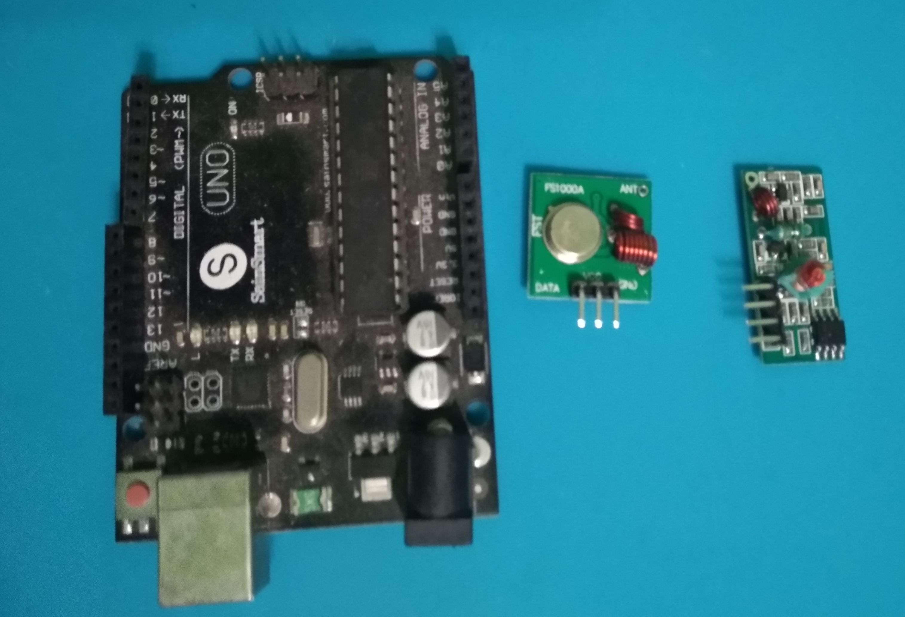
I will try to explain everything in an easy way. So what do we need to hack a device like this? First we need an Arduino. For the preparing part it is better to use an Arduino Uno or Mega which are easily available to buy. Then we will need some wires. We should not forget about the 433Mhz RF Decoder Transmitter/Receiver.
Tools and stuff we need:
- Arduino Uno/Mega
- 433Mhz Transmitter
- 433Mhz Reciever
- Few jumper wires
The receiver and the transmitter are separate modules,that will come in handy later. Now we need to install Arduino IDE for which you can find a step by step guide here:
Installation guide for Windows
Sniffing
So, now we have the IDE. Perfect. Next, we need the library mentioned below for the 433Mhz module to work. You can download it right here:
All you need to do is to unzip this file and extract to the library folder in your installation directory. (Eg: C:\Program Files\Arduino\libraries\ )
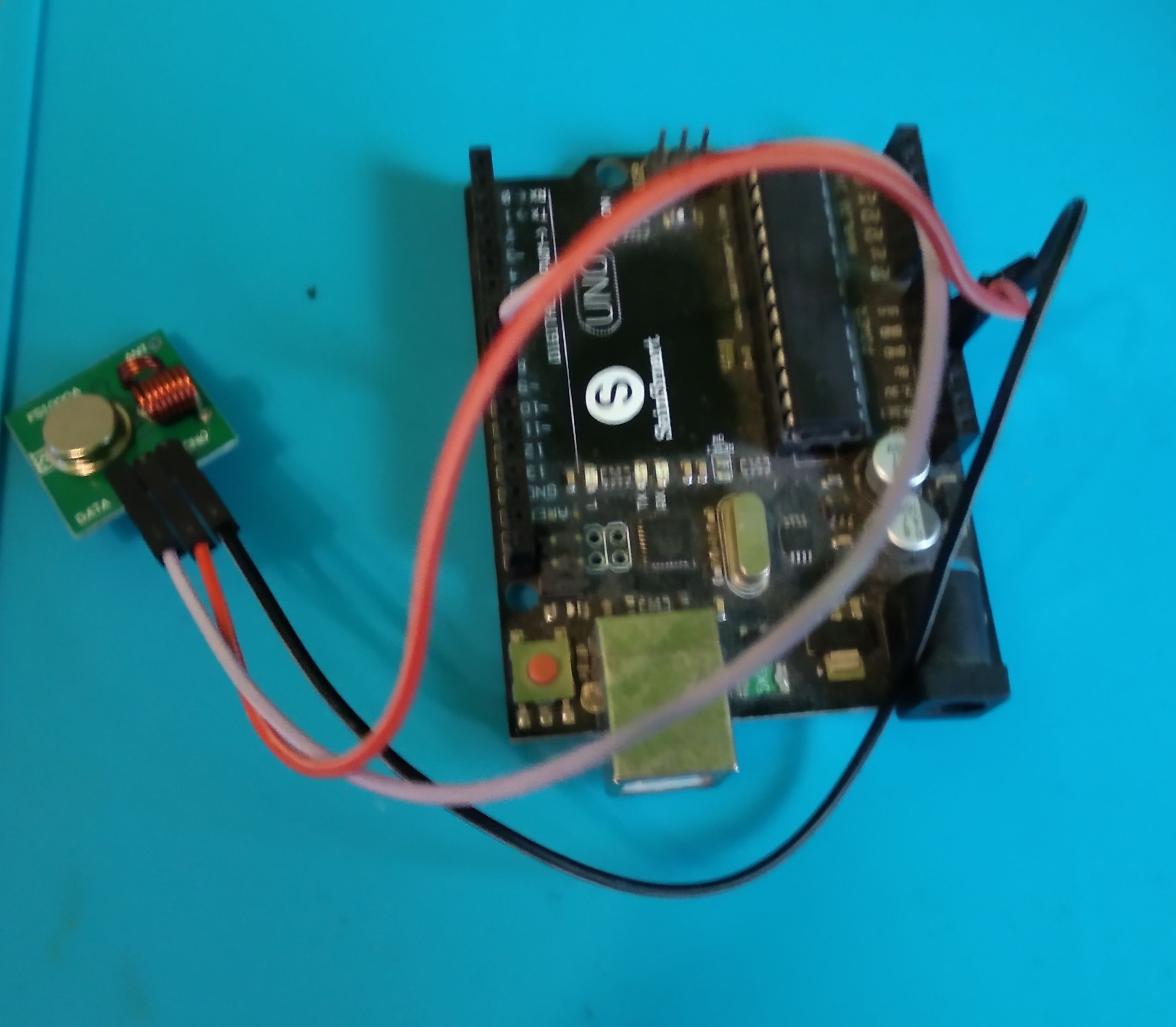
So everything is set up. We need to connect the arduino to the module and the arduino to the pc. The bigger one is the receiver with 4 pins. GND -> GND VCC → 5v The Data pin closer to the GND will go to the arduino pin 2. Just above the TX.

The next step is to get the program to the arduino. It is really easy, thanks to our library. Just go to File –> Examples –> rc-switch and click on REceiveDemo_Simple. The project is loaded into the workspace. I’ve explained the code in the comments shown below.
#include <RCSwitch.h>

RCSwitch mySwitch = RCSwitch();

void setup() {
  Serial.begin(9600); //Begin serial port communication with a baud rate of 9600. Important for watching the incoming data on the computer.
  mySwitch.enableReceive(0);  // Receiver is on interrupt 0 => that is pin #2
}

void loop() { //need an infinite loop so the Arduino keeps running
  if (mySwitch.available()) { //only start to write when there is data available

    Serial.print("Received Data");
    Serial.print( mySwitch.getReceivedValue() );
    Serial.print(" / ");
    Serial.print( mySwitch.getReceivedBitlength() );
    Serial.print("bit ");
    Serial.print("Protocol: ");
    Serial.println( mySwitch.getReceivedProtocol() );

    mySwitch.resetAvailable();
  }
}
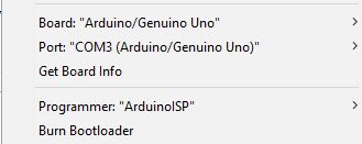
Before uploading the code to the Arduino, you need to check if everything is correct. Go to Tools Menu and it should look like the picture below.
COM port number does not matter. It is probably automatically set up by the IDE. Click on upload. After it is done, click on the magnifying glass icon. That is the serial monitor. That is where you can actually communicate with the arduino. Down in a dropdown box you will see the baud rate. Remember that we set a baud rate 9600 in the code? You should select 9600 just like there. All set up, now if you use the remote control it will detect the signal. You should see something similiar to this when a signal is detected.
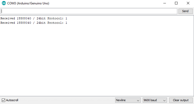
Remember 1 detection is not always 100% so try it a few more times. Now that we have the code ( for me it is 15588040) we can try to re-play it and see if anything changes.
Replay
This will be almost the same. Grab the transmitter and wire it up like: VCC –> 5v GND –> GND Data –>pin 10
To replay the signal you need to write a simple code. Go to File –> Examples –>rc-switch and select "send demo". Here we need a little bit of editing. I deleted everything in the loop except the send decimal line and a wait. Here is the code I used:
#include <RCSwitch.h>

RCSwitch mySwitch = RCSwitch();

void setup() {

  Serial.begin(9600);
  // Transmitter is connected to Arduino Pin #10
  mySwitch.enableTransmit(10);
}

void loop() {
  mySwitch.send(15588040, 24);
  delay(1000);
}
Save and upload the code just like you did with the reciever (change the number 15588040 to the number you sniffed). BOOM! Now you actually have your very own remote control working just the way you wanted it to! For me it is the lights. I can turn them on and off with my own arduino 433MHz transmitter. For the dentist, it would be the door which I could open just like that.
So, what's next?
This was an introduction of how to sniff the basic codes of a remote control on 433 MHz band and replay the same data. It is already capable to open some doors, turn off some lights and many more. Either way, we will update this project in the future and make it more useful. In the next part of this blog series, we will be trying to bruteforce the secret code of the remote control using an arduino again ;)